Pages

Friday 13 December 2013

Simple GPIO API

Practically with every project, I buy a new device - with which I need to familiarize myself. Most of the time those are devices using already very well known buses like I2C, OneWire or SPI. But from time to time it's a parallel device with a very specific interface. There's a need for the driver then. There are two ways: the easy one - get the driver from the internet and use it - now don't get me wrong that's a perfectly good way to solve the problem - your device is up and running pretty fast and you do not have to worry about it, since most of the problems have been already taken care for you.

The hard way is to write the driver yourself. Now a question arise why to do it in the first place ? The are a couple of reasons for that. First of all - you want to learn something - most obviously you will, since you will have to learn about the device thoroughly. Second - you want to make it smaller/faster - that's more pragmatic reason, since the downloaded driver may not represent the "state of the art" or simply maybe bloated with features which are not desired or simply not needed. Another good reason is that the available drivers are simply not compatible with our already existing program and making both fit one to each other may take more time and effort than simply creating a new driver from scratch.

OK, but what does this all have in common with GPIO lines ? Devices use GPIOs, in case we need to "bit bang" some sort of communication standards will operate on GPIOs

Why not use the PORT{B,C,D} directly though ? Because it will be pretty hard to change the code when you decide to move your device to different pins. In that case most people use preprocessor like that:

#define PORT PORTD
#define DDR DDRD
#define INP PIND
#define PIN 6

... and in the code

DDR |= _BV(PIN);
PORT &= ~_BV(PIN);
PORT |= _BV(PIN);

... and so on. For a simple case that's pretty good approach, but if we have a lot of lines that may become a problem since the pin declaration becomes very complicated and extensive. It can be done a lot slicker and elegant. In order to have complete control over a port we need 4 values: the port's data register (PORTX), the port's direction register (DDRX), the port's input register (PINX) and the pin number. OK, but going through the datasheet a nice dependency occurs. The PORT addresses are consecutive:

PORTB = 0x05
DDRB = 0x04
PINB = 0x03

So, having only the PORTX address, we are able to determine every other needed memory location. Let's make some macros for that:

/**
 * @brief get pointer to DDR register from PORT register
 *
 * @param __val pointer to PORT register 
 *
 * @return pointer to DDR register
 */
#define GET_DDRX_FROM_PORTX(__portx) \
(__portx - 1)


/**
 * @brief get pointer to PIN register from PORT register
 *
 * @param __val pointer to PORT register 
 *
 * @return pointer to PIN register
 */
#define GET_PINX_FROM_PORTX(__portx) \
(__portx - 2)

It's pretty simple to use them:


volatile uint8_t ddr = GET_DDRX_FROM_PORTX(&PORTB);


Now, we need only the PORTX address and the pin number. We can make it even more flexible and universal. Let's desribe a single gpio:


typedef struct _gpio_pin {
volatile uint8_t *port;
uint8_t pin;
} gpio_pin;


Now, we can declare a single pin like that:

gpio_pin x;

x.port = &PORTB;
x.pin = 3;

At the moment it's not very convenient to use this type, since just to change the value we need to:


*x.port &= ~_BV(x.pin);


But we can create some macros for that as well:


#define GPIO_CONFIGURE_AS_OUTPUT(__gpio) \
*(GET_DDRX_FROM_PORTX((__gpio)->port)) |= _BV((__gpio)->pin)

#define GPIO_CONFIGURE_AS_INPUT(__gpio) \
*(GET_DDRX_FROM_PORTX((__gpio)->port)) &= ~_BV((__gpio)->pin)


#define GPIO_GET(__gpio) \
(*(GET_PINX_FROM_PORTX((__gpio)->port)) & _BV((__gpio)->pin))


#define GPIO_SET_LOW(__gpio) \
(*(__gpio)->port) &= ~_BV((__gpio)->pin)


#define GPIO_SET_HIGH(__gpio) \
(*(__gpio)->port) |= _BV((__gpio)->pin)


#define GPIO_TOGGLE(__gpio) \
*(GET_PINX_FROM_PORTX((__gpio)->port)) = _BV((__gpio)->pin)


OK. Now we've everything we need. Let's have a look at a full blinking LED example using this API. The example presents two options. First using the TOGGLE call, second using the LOW/HIGH calls. In order to test the second one, you should comment out the first one.


This all may look unnecessarily  over complicated but it's very useful when trying to write a flexible driver. Just imagine that you wrote a great driver for an LCD display. You used in your device on let's say on a couple of pins of PORTB, then you want to use it again in a completely different device on a completely different set of pins - there's not a problem at all - since thanks to this abstraction you just need to redefine the pin numbers. The driver uses the GPIO API and is completely hardware independent ! That's a great advantage !

I hope that this tip was useful. I'm currently working on the software for one of my standalone devices - Clock with Thermometer - want to polish it as much as possible and implement some cool ideas so, it takes pretty long. Can't wait to publish some details regarding this project


Sunday 17 November 2013

RTC without RTC ? How good is my crystal ?

Clock - I think that it's the most popular idea for a project with the MCU. It's not that hard from both software and hardware side to realize but not that trivial as well, not mentioning the fact that once realized it sits somewhere in the house, constantly reminding about itself and brings a kind of satisfaction :). There are a lot of options really to implement, a buzzer alarm, perhaps a thermometer, display and buttons servicing, perhaps maybe even serial port usage for NTP synchronization. But ...

The most challenging thing - like in every clock is the time reference source. There are a couple of options:

  • well calibrated frequency source acting as an interrupt source
  • Real Time Clock module with external crystal ( < 20 ppm )
  • internal clock


These days RTC chips are so cheap and widely available that they are really the only reasonable choice, but if we're only planning to play around a bit with the software without paying much attention to accuracy and just for the sake of curiosity let's check how good the crystal to generate the system clock on the Arduino board is.

System Clock


System clock is generated using an external 16 MHz crystal. This crystal is not ideal, although it's quite stable - it may be surprising that it doesn't resonate exactly with the referenced frequency. In fact this frequency is a little bit different. 

Stability


A crystal accuracy is measured with ppms (parts per million). A typical crystal used to generate a system clock is something around +/- 50 - 100 ppm. Let's assume 80 ppm. The day has:

day = 24 * 60 * 60 = 86400 s

the hour

hour = 60 * 60 = 3600 s

If we would want to use this crystal as a reference for the clock application our clock would loose/gain:

per day:

86400 * 80 ppm = 86400 * 0,0008 = 6,91 s

per hour:

3600 * 80 ppm = 3600 * 0,0008 = 0,288 s

On the worst case it would be around 9 s per day. That's not that bad for a toy project.

Resonance frequency


Although the stability is quite satisfying, information about the exact resonance frequency is needed. How different is the resonance frequency of a typical 16 MHz crystal from the referenced 16 MHz ?

Using some code I can roughly measure it without using any laboratory equipment like frequency meters or oscilloscope. In fact I don't have access to this hardware and for most of the simple projects which I present here, although it would be helpful it's not a must.

The simplest way to estimate the crystal frequency is to use the code already created in libpca. Let's generate a tone of let's say 1 kHz frequency with a libpca beeper API. Now, Instead of connecting the buzzer I'll connect the pin to my laptop's microphone input directly and try to record it. The code is trivial:

Recorded signal:

1 kHz square signal recorded from OC0A pin.

This rough measurement shows that the full period took 45 samples at 44,1 kHz sampling rate, this gives the period of ~1,02 ms. The crystal clock period is 16000 shorter. After dividing the measured period of 1 kHz beep by 16000 and converting it to frequency, the answer is:

f =~ 15,68 MHz.

This means that our clock application will loose seconds. Every second measured will in fact be a 1,02 seconds in reality. This gives 1.2 seconds behind after every minute ! Of course the measurements done cannot be taken very seriously since they are done very inaccurately and without a proper tools, but keeping them in mind, let's write a simple application and see how much our "clock application" will be wrong from real time.


The above code is self explaining more or less, the "epoch" variable is incremented in the interrupt service routine every second (since interrupt happens every 1/256 s and epoch is incremented only when the cnt variable wraps). The time is send via Serial Port as a string.

After flashing it and running. I did some comparison between the measured time and the "real" time with a stopwatch. After an hour, Arduino has been a second behind. The crystal instability (80 ppm) results in 0,3 seconds behind. Assuming 0,7 second lost per hour I can roughly estimate that my crystal is less than 16 MHz by something around 3 kHz. So, it's more like 15,9968 MHz.

Conclusion


When building a real clock application RTC chip is a must, the system clock won't provide enough accuracy to be considered as a frequency reference good enough. Not mentioning the obvious advantage of having the RTC - the time is counted even if the main CPU is not powered, since most of them have a backup lithium battery circuitry.

The methods used to estimate the Crystal's resonance frequency cannot be treated serously with any level of confidence and used for a real production purpose, since they present no practical level of accuracy and the results are only a general hint.

Friday 8 November 2013

Arduino PWM Audio DAC

This post is an addendum to the previous one. To make our lives (as a software developers) even more easier it is possible to recreate a real audio without even having to built the R-2R ladder. Atmega328 comes with a PWM capable timers and they're good enough to produce audio quality analog signal.

PWM fundamentals


I'm not going to go into details about PWM digital to analog conversion, on this blog I focus on my code and do not intend to cover the theoretical background very thoroughly. Please take some time and familiarize yourself with the PWM theory explained on those sites:

  1. Open Music - PWM DAC
  2. Open Music - Dual PWM
  3. Open Music - Distortion Analysis
  4. Open Music - PWM Tutorial

In general every PWM DAC can be described by a PWM frequency - fpwm (the frequency of the squarewave generated - which is constant) and the PWM bit resolution - bitres (which describes the granularity with which we can control the duty cycle).

All of three Arduino's Timers are capable of generating PWM signal. I'll focus of course on Timer1 since it's the only 16 bit timer. As mentioned above we have two properties to configure - the PWM frequency - fpwm and the bit resolution. The signal theory says that the fpwm should be at least two times higher than the highest frequency in our signal. How to calculate it and what is the highest possible we can achieve ? To answer that some details from the datasheet are needed and in fact an understanding of how Atmega's Timer really works.

Timer in PWM mode


Using either Fast (FPWM) or Phase & Frequency Correct PWM (PFPWM) the timer counts up from 0 to value in either OCR1A or ICR1 register (I'll use ICR1 to define the frequency, since obviously the value in OCR1A will control the comparator and in result the duty cycle). This means that ICR1 defines the TOP value for the timer (and thus implicitly defines how often the timer will overflow). The PWM frequency will be defined as:

Fast PWM:

fpwm = fclk / [ N * (1 + ICR1) ]

Phase and Frequency Correct:

fpwm = fclk / [ 2 * N * (1 + ICR1) ]

where N is prescaler.

I want the fpwm to be as high as possible so, obviously the prescaler will be configured to 1. It may not be visible at first glance but the fpwm has a major implications on the bit resolution as well. The value in OCR1A will control the duty cycle - it can't be any bigger than the value defined in ICR1 - which defines the frequency. if it will be higher than ICR1 than the timer simply will never reach it and the result will be a flat line - 100% duty cycle. It's more clear if you look at the picture

Principles of PWM with Atmega's Timers.

It's clear now that the demand for highest possible fpwm as well as highest possible bitrate is self contradicting. A golden merit must be established. In general it's worth to sacrifice some of the bit resolution just to increase the fpwm. I'll talk about real values in just a moment.

... Need more bandwidth


Indeed, just as previously the main bottleneck is the Serial Port. I did some tests pushing it to it's limits and it seems that the highest possible baud rate I can get is 230400. I don't want to change the firmware in Arduino's Atmega16U2 chip responsible for USB <-> serial communication, so I guess I'll have to live with this constrain and try to squeeze as much of the serial port as possible anyway.

230400 is not that bad. It's 23kB per second. What I can play with it ? There are a three options really (not mentioning the compressed formats - but that's a completely different story):

  • 16 kHz, 8 bit = 16 kB/s
  • 8 kHz, 16 bit = 16 kB/s
  • 22 kHz, 8 bit = 22 kB/s 18 kHz, 8bit = 18 kB/s
22 kHz sounds pretty good. This means that the highest frequency that can be recreated is around 11 kHz. As it will be shown later the bit resolution doesn't have that much of a spectacular influence on the quality, The bit resolution defines the so called "noise floor" which in simple words means that the lesser the bit resolution the noisier the signal will be and it will be impossible to recreate some very quiet - low amplitude sounds since they will drown in the digital noise itself. In this case, having the sampling rate as highest as possible is crucial.

22 kB/s doesn't leave much time margin though. It's almost feeding the DAC directly from the USART without much of a buffering - this may be a source of glitches and noise as well, not mentioning the glitches that will happen if the transmission is unsuccessful. The MCU will be pretty busy. In fact the USART is too slow to provide the data on time with this sampling rate. The highest I could get is 18 kHz unfortunately. 18 kHz is an absolute limit for the USART and even at that speed occasionally some glitches may happed

Data delivered to slow. A short moment of silence.

Anyway it's pretty good though, 9 kHz of audible bandwidth should sound good.

PWM frequency and bit resolution


Going back to the PWM frequency. I'll use the Phase & Frequency correct PWM mode. Our requirement is to play an audio with highest frequency up to 9 kHz. The fpwm must be higher than 18 kHz. We'll base our calculations on the bit resolution though, since we're not going to play anything above 8 bits (per PWM channel). Assuming that OCR1A must have an 8 bit resolution so ICR1 must be configured to 256. Taking those values into consideration:

fpwm = 16 MHz / [ 2 * 1 * (1 + 255) ] = 31,25 kHz

which is 3,4 higher than the highest frequency of the signal - that'll do.

16 bit playback


One of the options that I have is to play 16bits 8 kHz audio. Now, how to do this when just a paragraph before I configured the PWM resolution to 8 bits ? It's actually pretty easy. Atmega has two comparators per timer OC1A and OC1B. Each of them has an independent register OCR1A and OCR1B which value is constantly compared with TCNT1 value. The PWM duty cycle of the waveform on OC1A and OC1B pins is controlled by configuring OCR1A and OCR1B to appropriate values. In fact we can sum the signal from those two 8 bit outputs using resistors to form one combined output 16 bit output. The trick is that the resistor for the least signifficant byte has 256 smaller value than the one for the most signifficant byte - by natural way the levels of those two PWM outputs are shifted.

Playback


The playback loop is slightly different than the one for R-2R ladder. Now instead of pushing the data to the ports, it is "pushed" to the OCR1A timer registers:


you noticed the MODE macro. The software; during compilation, can be configured into any of the mentioned mode

  • #define MODE_8K_8B 0
  • #define MODE_8K_16B 1
  • #define MODE_16K_8B 2
  • #define MODE_18K_8B 3

By default MODE is configured to

#define MODE MODE_16K_8B

Dependently on the mode selected (16bit or 8 bit) the sample value is copied only to OCR1AL or to both OCR1AL and OCR1BL

The Circuit


PWM requires a couple of components forming a low pass filter in order to get rid of the PWM carrier frequency. The PWM frequency is 31,25 kHz, but we don't need anything really above 9 kHz, so the filter values should be:

f = 1/ [ 2 * 3,14 * R*C] = 1/[2 * 3.14 * 3k9 * 4n7] = 8,69 kHz 

The filter itself:

PWM filters for both PWM channels


PWM filters on the breadboard.

Software


As mentioned the software is more or less identical as for the R-2R ladder. It has only been enhanced to support conversion into couple of different formats instead of one (8kHz, 8 bit) and the baudrate has been increased to 230400 bps. As previously everything is done in binary manner to squeeze out everything that the USART can provide. The PWM configuration is being done by the libpca functions, there's no need to go into details about that, all the settings are standard, nothing extra out of ordinary. The timer is by defauilt configured into Phase & Frequency correct PWM mode, but it's possible to play with this setting in the code to compare the quality.

#if MODE == MODE_8K_16B
/* tpwm_fpwm_init(E_TIMER1, E_PWM_DOUBLE); */
tpwm_pwm_init(E_TIMER1, E_PWM_DOUBLE);
#else
/* tpwm_fpwm_init(E_TIMER1, E_PWM_SINGLE); */
tpwm_pwm_init(E_TIMER1, E_PWM_SINGLE);
#endif

How to use it


On the PC side, as previously one should use the player.sh script. The syntax has been changed slightly. The first argument is the mode, the rest are the audio files

player.sh <16b | 16k | 8k | 18k> <audiofile(s)>

The options are self explaining I think, In order to use the 16 kHz mode we should invoke the script like this:

./player.sh 16k myfile.mp3

One must remember to adjust the Arduino's serial port name in the wpwm.pl script accordingly if needed.

On the Arduino side, we must select the mode which we want to try by adjusting the MODE macro in main.c file (as mentioned previously). After compiling and flashing the firmware, one should be able to successfully use the player script in order to hear some music. 

I connect my Arduino directly to the MIC-IN of my laptop in order to record the sound - I don't use any amplifiers whatsoever.

The software as usual is available either as a snapshot from here (containing libpca snapshot and the project itself) or it can be clones from my github repositories:

git clone git@github.com:dagon666/avr_Libpca pca
git clone git@github.com:dagon666/avr_ArduinoProjects projects

cd projects/dac

Building & flashing:
make
make install

Let's hear some music finally


Just as expected the difference between 8 and 16 bits is almost unrecognizable. Only at the begining when the dynamic is quite low, the noise level for 16 bits is signifficantly lower. The most spectacular change comes along with the sampling rate - the higher the better.


Throughout the clip some glitches are noticable from time to time - they're the result of corrupted frames (CRC does not match) or simply the fact that the data was not delivered on time (18 kHz mode). In 18 kHz the USART is really operating on it's limit (as well as the CPU - which must service the RX interrupt), I mostly wanted to demonstrate that it's possible to go that high, but the audio is far more stable and less glitchy in 16 kHz mode.

Saturday 2 November 2013

Arduino R-2R ladder Audio DAC

There is a lot of projects out there which use R-2R ladder and an Arduino to recreate sounds from either SD card or short audio clips programmed directly to MCU's flash memory. Although using SD card is fairly reasonable and provides a lot of flexibility it's not very challenging (from the software point of view) and it requires some additional hardware. Believe it or not we already have all the needed hardware in the Arduino itself.

Assumptions


In this project I'll play mp3 or any other multimedia files from the PC using Arduino. Bellow are the details:
  • Play PCM 8kHz 8bit Audio with Arduino
  • Audio samples will be transfered via USART from the PC in binary format using SLIP
  • Audio files will be decoded on the PC side and only the RAW data will be send to Arduino

Timing


Arduino is a powerful machine, powerful enough that it's possible to play audio with even higher sampling rates and bit-resolutions than assumed above, the bottleneck in this case is the Serial Port. Assuming that I'll use the highest standard USART speed available which is 115200 bps (8 data bits one start bit and stop bit = 10 bits to send a byte) it's possible to send up to 11520 bytes per second. In order to play a second of 8 kHz 8 bit Audio I need to have at least 8 kB of data. So the USART is around 30% faster as a data producer than the audio samples consumption rate, which means that 8kHz standard sampling rate is the highest I can get. 

The timing is crucial thing in this project. The data must be buffered but what kind of buffer do I need to have ? At first I thought that the bigger the better, but that's not exactly true. Accordingly to assumptions in implementation of the SLIP protocol in libpca, one SLIP frame can carry up to 256 bytes of data, we must not forget that this transfer is not instantaneous it takes time and we're in the middle of the playback not really knowing (at the PC side) how much audio samples have already been consumed (the consequence is that it's hard to tell how much space is available in the buffer). If the buffer at Arduino side doesn't have enough data to hold the new upcoming chunk - the data will be lost and we'll hear an audio glitch - and that situation for sure will happen since we're sending faster than consuming. 

First approach that came to my mind is to simply wait after each data block in order to be sure that there will always be enough space in the buffer (since most of the data will be consumed). Let's think about it for a moment and evaluate some rough timing calculations.

  • playing 256 samples takes 1/8000 * 256 = 32 ms
  • sending 256 samples takes 256 + 2 (SLIP END characters) / 11520 = 22 ms 

The second calculation does not take into consideration any additional SLIP ESCAPE characters that may be included. But more or less I have a 10 ms I can wait after sending the chunk before sending another one, right ? WRONG. Those calculations do not consider that during those 22 ms when we were sending the data already something around 176 samples have been played (68% of the data). OK, so if I'll wait 32%*10ms = 3.2 ms then it should be fine, right ? WRONG again. By waiting, everything that is done is only hopelessly trying to make the data transfer speed equal to the audio consumption rate. It's impossible to synchronize ideally those two independent processes since there are so many factors that can have it's influence on the timing that all the efforts by definition have simply no point. If the sending rate will be too low, the audio will be chopped since there will be gaps in the playback, if the data will come too fast, there will be no space available and will have drop the data from time to time.

It's even worse. Let's look on the slip_recv function prototype:

uint8_t slip_recv(uint8_t *a_buff, uint8_t a_buflen);

It takes a pointer to a buffer for the incoming data, since this is a transmission buffer it can't be used to realize another transmission until the data is completely consumed. That means that after the reception we must COPY the data from the frame to the proper audio buffer. Which makes the timing COMPLETELY unpredictable with the required precision.

How to cope with this situation then ? First of all we cannot afford to copy the data from one buffer to another - it's simply a waste of time and by clever memory organization this problem can be easily eliminated. The playback must be done from the transmission buffer directly. But how to perform the transmission and audio playback using the same buffer in the same time ? It's actually pretty easy. Have a look:

I have four transmission buffers (let's call them buffer banks) each of them holding 64 samples. The audio will be played directly from the samples table. The beauty of the picked size is that

64 * 4 = 256

which means that the audio data can be addressed using a single byte, the following way:

sample = p[(g_tail >> 6) & 0x03].samples[g_tail & 0x3f];
g_tail++;

Since g_tail is an 8 bit variable 2 upper bits select the "bank" (0-3), and the rest, addresses the audio data (0 - 63). I address both the buffer bank and the audio data with a single variable. It more or less looks like using a single continuous buffer.

When receiving data I track which buffer bank is free (1-4) and I write to it. The playback happens from the previous buffers. If there is no free buffer available I send a "WAIT" command to the PC so it can wait a little while (a time shorter than the time needed to consume 3 buffers = 192 audio samples, basically the time must be longer than 8 ms (consume 64 bytes = 1 bank) and shorter than 24 ms). I chose 1,9 ms which lasts for around 15 audio samples. It's too short isn't it ? No it's not. Let's assume 2 ms of explicit waiting (due to the function inaccuracies) + time needed to receive the "WAIT" string through the Serial Line: 350 us which already makes it let's say 2.5 ms not mentioning any other processing times and of course the time needed to transfer 64 bytes block >= 8 ms, which in total gives at least 10,5 ms. Of course the time is much more longer (SLIP special characters have not been taken into consideration and as mentioned indeterminable processing time has been omitted as well).

The transmission/consumption process is depicted bellow:

Transmission of binary frames through the Serial Port and new data placement in the Arduino's buffers.


Playback


Let's talk about how to play the samples ? I use timer in CTC mode and play the samples by placing them on the port directly, but again there's a little catch here as well. The only "full" 8 bit port available on Arduino is PORTD, unfortunately we can't use it's two lower PINS 0,1 since they are shared with USART and I'm using USART as a data source. Because of that The bottom part of the byte (bits 0 - 5) is placed on PINS 2-7 of PORTD and the remaing two most significant bits (6 - 7) are placed on the adjacent PORTB. This may have an influence on the audio quality since placing the data on two ports is not an atomic operation - first we place one piece of data - which in effect generates some sort of voltage on the R-2R output, then we place the remaining piece of data on the other port - this will probably generate a high frequency glitch for every sample. Have a look on the schematics.


R-2R Ladder


A word about the Ladder itself. I chose a value of R = 5k. I had more in mind the 2R value = 10k which is the standard one. I had 4k7 resistors laying near hand so I decided to use them. It wasn't a good idea. The R-2R relation must be as good as possible. It's best to use the same resistors for both R and 2R and connect two of them in parallel to form a R value, so in my case R = 5k (two 10k connected in parallel) and 2R = 10k. I took some measurements using Arduinos ADC (the R-2R ladder output connected to the ADC) and below are the results. It's pretty visible that using 4,7k and 10k for R-2R ladder is a bad idea.

R-2R = 4k7-10k Ladder signal response (sawtooth).

R-2R = 4k7-10k Ladder signal response (sine wave).

Major differences when using two 10k in parallel as 5k.

"Steps" visible anyway - the curve magnified.

R-2R Ladder with 4k7 and 10k resistors. Work in progress.

R-2R Ladder with 10k restistors connected in parallel.

R-2R Ladder Schematics.

The source code.

Arduino Side


Arduino program is pretty simple. I already mentioned that samples are played in the timer interrupt. Besides that a standard data collection algorithm happens in the while loop in a very similar fashion to the one from the Arduino MIDI player.

The function collecting the samples, takes a pointer to the destination buffer. The buffer is selected from four available by using 2 most significant bits of the g_head counter. g_head & g_tail indexes realize a queue on the buffers. The g_tail is incremented by the timer interrupt whenever new sample is played. The g_head is incremented along with new data received. As long as g_tail != g_head I know that there is still data available in the buffers.

serial_collect_samples((void *)&p[(g_head >> 6) & 0x03]);

A word about the sample collect function


First thing is to check if number of available samples is higher than 192 (3 banks) if yes, then the "WAIT" command is send, to tell the PC side to refrain from sending new data for a while. The slip_recv call is blocking. It will block until new data has been collected, after CRC verification and making sure that the data is genuine the g_head index is incremented by the number of samples received in the frame.

PC Side


Perl script is responsible for feeding Arduino with data. This script accepts a 8 kHz 8 bit WAVE file as an input. It's pretty straight forward and similar to previous script for the Arduino MIDI player. First it initialize the Serial port, then it tries to open the WAVE file and read it's header. After that is successful I read 44 bytes of header and unpack them.

die "Unable to read WAV header\n" 
    unless($offset = read $g_fh, $header, 44);

my @header = unpack "a4la4a4ls2l2s2a4l", $header;

It get's more sense if you look on the WAVE file header:


So, the unpack call extracts RIFF file id, the WAVE file format and the rest of the header fields. The purpose is to detect if it's a WAVE file and if it has the only compatible sampling rate and bit rate. Once that is confirmed, the script goes to the "transfer loop". If there is no "WAIT" command received from Arduino it simply reads the 64 byte data chunk from the file and feeds the Arduino. If "WAIT" has been received, the script will wait for around 2 ms (1900 us). The loop continues until the whole file is processed. The frame contains two bytes of CRC, one byte indicating how many samples it conveys and the samples themselves.

Although it's completely fine to use this script directly I use it in a wrapper (I could've made everything in the single script, but I was too lazy :)). The "player.sh" shell script accepts any audio format as an input it uses sox to convert the provided audio file to an intermediate WAVE file which then will be provided to Perl in order to be played by Arduino. It's a lot more useful than converting the files manually every time.

How to use it ?


The whole project snapshot can be obtained here. One can fetch the newest version of libpca and the project itself from my public GitHub repository as well. The snapshot and the GitHub version have a slightly different Makefile, paths to the libpca are a little bit different, everything else is exactly the same.

GitHub


git clone git@github.com:dagon666/avr_Libpca pca
git clone git@github.com:dagon666/avr_ArduinoProjects projects

The project resides under dac directory. After navigating to it. One should change the branch to r2r_dac:

git checkout -b r2r_dac origin/r2r_dac

Snapshot


Download and unpack the snapshot from here

... the rest is common:

Build and flash the Arduino firmware:

cd projects/dac
make
make install

Launch the player.sh script with an audio file as a parameter:

$ ./player.sh audio.mp3

The Presentation


Finally we can play some audio. The video presents an Arduino playing mp3 of my metal project Tangible Void - you can check it out on youtube - here.


Saturday 26 October 2013

Arduino MIDI Music Box

It's time to do something useful with our small 8-bit computer. Music box is a fun and easy project. It's not demanding from the hardware point of view but it can be a little bit tricky from the software point of view itself - ideal project to learn a lot and not to spend the whole day soldering. What we will need: 

  • an Arduino (of course) 
  • Piezo buzzer

 ... and that's all. Now a couple of words of what we want to achieve. 

Requirements 


Let's point them out:

  • play monophonic melodies by generating tones (1 channel MIDI instrument)
  • the notes will be send by the PC through the serial port 
  • our musicbox should be visible to the PC as a MIDI port 
  • be able to use MIDI player of choice on PC to play MIDI files on our musicbox 


The requirements are specified. Unlike most of the simple projects around which play the same melody everytime, which most of the times is hardcoded in the program memory and in order to change it one must modify the tone frequencies and the timing between them and then re-flash the Arduino, our musicbox will simply act as a simple MIDI device and become a "MIDI sink" for incoming serial data. That means that more or less we can play any MIDI file with it that comes in our hands. The only limitation is the number of channels - the firmware which I'm going to discuss will play only one - the user will have to select what channel data should be send & played, but in general it's not impossible to enhance the implementation to support more, for demonstration purposes one is enough though. 

Technologies 


I need to discuss what kind of tools and technologies will be used. No matter how trivial a musicbox can look in the first place there will be quite a lot going on under the hood. Here are the things that will be used (in terms of software) on the Arduino side: 

  • beeper module from libpca - the timer will be used for tone generation 
  • SLIP module from libpca - the data will be send in binary format in SLIP frames from PC to the Arduino 

Everything has been already covered in my previous posts on this blog. If you're following the blog any of the above require no explanation. At the time being creating a more sophisticated project like this one is only a matter of putting the building blocks together. On the PC side I will use Perl to do the dirty work. No matter what you have heard or have been told, Perl is a great language far more superior than Python and I hope that again I'll prove it to every of you. Things that will be needed: 

  • Device::SerialPort - serial port communication 
  • MIDI::ALSA - for doing all the MIDI dirty work 
  • Digest::CRC - to calculate CRC checksum of the outgoing data PC side


PC side


Let's start with the PC side first. The Perl script will register new MIDI port and wait for the data written to it which then will be send through the Serial port to Arduino - pretty simple. The data I'm interested in from the MIDI stream incoming are so called "note_on/note_off" events. Unfortunately their not exactly in a format convenient and appropriate for this project. The note_on event defines the beginning of a particular not (a trigger to start generating tone of given key), we should stop generation when receiving note_off. This is not acceptable since it blocks possibility to generate any other tone in between and we would have to track when to really stop the generation on each incoming note_off event. 

Fortunately enough again Perl and CPAN saves the day. The MIDI::ALSA module defines a notion of "score" - a set of midi tracks in which every event has it's own length defined, so instead of two events note_on/note_off we have only one - note, which provides the following information:

{'note', start_time, duration, channel, note, velocity}

Exactly what we need. The bad news is that it doesn't work very well. In fact it seems that duration has some constantly increasing value along with the position in the MIDI file and in result isn't very useful at all, but at least instead of processing two events we have only one. From the data above I'm interested only in the event type -> 'note' the 'note' itself of course and the channel - I'll filter the data from one or couple of channels only to be send and played by Arduino since it would produce a complete chaos if we would want to try to play everything using only one instrument at once.

Since we will be sending the frequency to the Arduino, we need to convert the MIDI note number (0-127) into frequency domain. After doing a quick Google search for MIDI note frequencies I come up declaring the following array:

# midi notes
my @notes = (
8.1757989156,
8.6619572180,
9.1770239974,
10.3008611535,
10.3008611535,
10.9133822323,
11.5623257097,
12.2498573744,
12.9782717994,
13.7500000000,
14.5676175474,
15.4338531643,
16.3515978313,
17.3239144361,
18.3540479948,
19.4454364826,
20.6017223071,
21.8267644646,
23.1246514195,
24.4997147489,
25.9565435987,
27.5000000000,
29.1352350949,
30.8677063285,
32.7031956626,
34.6478288721,
36.7080959897,
38.8908729653,
41.2034446141,
43.6535289291,
46.2493028390,
48.9994294977,
51.9130871975,
55.0000000000,
58.2704701898,
61.7354126570,
65.4063913251,
69.2956577442,
73.4161919794,
77.7817459305,
82.4068892282,
87.3070578583,
92.4986056779,
97.9988589954,
103.8261743950,
110.0000000000,
116.5409403795,
123.4708253140,
130.8127826503,
138.5913154884,
146.8323839587,
155.5634918610,
164.8137784564,
174.6141157165,
184.9972113558,
195.9977179909,
207.6523487900,
220.0000000000,
233.0818807590,
246.9416506281,
261.6255653006,
277.1826309769,
293.6647679174,
311.1269837221,
329.6275569129,
349.2282314330,
369.9944227116,
391.9954359817,
415.3046975799,
440.0000000000,
466.1637615181,
493.8833012561,
523.2511306012,
554.3652619537,
587.3295358348,
622.2539674442,
659.2551138257,
698.4564628660,
739.9888454233,
783.9908719635,
830.6093951599,
880.0000000000,
932.3275230362,
987.7666025122,
1_046.5022612024,
1_108.7305239075,
1_174.6590716696,
1_244.5079348883,
1_318.5102276515,
1_396.9129257320,
1_479.9776908465,
1_567.9817439270,
1_661.2187903198,
1_760.0000000000,
1_864.6550460724,
1_975.5332050245,
2_093.0045224048,
2_217.4610478150,
2_349.3181433393,
2_489.0158697766,
2_637.0204553030,
2_793.8258514640,
2_959.9553816931,
3_135.9634878540,
3_322.4375806396,
3_520.0000000000,
3_729.3100921447,
3_951.0664100490,
4_186.0090448096,
4_434.9220956300,
4_698.6362866785,
4_978.0317395533,
5_274.0409106059,
5_587.6517029281,
5_919.9107633862,
5_919.9107633862,
6_644.8751612791,
7_040.0000000000,
7_458.6201842894,
7_902.1328200980,
8_372.0180896192,
8_869.8441912599,
9_397.2725733570,
9_956.0634791066,
10_548.0818212118,
11_175.3034058561,
11_839.8215267723,
12_543.8539514160,
); # notes

Great, one problem less. 

The MIDI sequencer


A MIDI sequencer must be registered on the PC side to provide an output for MIDI playback software. It's extremely easy with MIDI::ALSA module and Perl:

MIDI::ALSA::client('Arduino MIDI Beeper', 1, 1, 0);

and that's all. I register a new sequencer with one input port and one output port. We can already see it in the system:

$ aconnect -oil
client 0: 'System' [type=kernel]    0 'Timer           '    1 'Announce        'client 14: 'Midi Through' [type=kernel]    0 'Midi Through Port-0'client 128: 'Arduino MIDI Beeper' [type=user]    0 'Input port      '    1 'Output port     '

Ok, we are almost done, all that's left is to take the MIDI data and send it to Arduino. Let's analyze the main program loop, again there will be some Perl trickery but I'll try to de-crypt everything which is not obvious to everyone not very familiar with Perl.

The call to MIDI::ALSA::input() is blocking, it means that we will wait on the first line for the MIDI event before we'll send anything to the Arduino - that's a good thing, that way we do not have to worry about the timing, the notes will be played as soon as they arrive. Next I detect if the incoming event does not define the MIDI file end - I exit the loop if that's the case. 

Next thing is to convert the MIDI event to a "score event". Next two lines simply skip to another loop roll if the event does not contain any useful information (it's either empty or it's not a 'note' event). Just for the debugging purposes I dump the event to the console. Going further I filter the events (by skipping them) if in the command line channels to be player are specified, if not then data from every channel will be sent. Later on I simply convert the MIDI note to frequency and because of the problems with getting the reliable event 'duration' information from MIDI::ALSA I simply define a fixed duration for every note in milliseconds (50 in this example). Next the data is being placed in the SLIP frame and sent to Arduino to be played. Arduino should return the data back (again just for debugging purposes) - and that's all.

Arduino Side


Basically all the hard work has been already done and is hidden in libpca. Please refer to my previous posts for more details, since every aspect and function used for this mini project has been already thoroughly discussed. 

Arduino firmware will be very simple, all that needs to be done is to simply receive the SLIP frame, verify it and play the note inside. Let's have a look on the message format first.

Each note is defined as a pair of numbers - frequency and the duration. Each packet coming from the host contains the CRC16 checksum, a byte denoting how many notes have been sent and the notes themselves. I decided that in a single packet it will be possible to send up to four notes - that would require some timing information for each note itself so even though it's possible to sent up to 4 notes in one shot in the final version of this project I'm always sending only one.

The listing bellow present a complete source for the Arduino firmware.


In the while loop it wait's for a new SLIP frame, verify the data integrity and play the notes from the packet. After flashing the Arduino we can finally do some tests.

How to use it ?


The whole project snapshot can be obtained here. One can fetch the newest version of libpca and the project itself from my public GitHub repository as well. The snapshot and the GitHub version have a slightly different Makefile, paths to the libpca are a little bit different, everything else is exactly the same. 

GitHub


git clone git@github.com:dagon666/avr_Libpca pca
git clone git@github.com:dagon666/avr_ArduinoProjects projects

Snapshot


Download and unpack the snapshot from here


... the rest is common:

Build and flash the Arduino firmware:

cd projects/musicbox
make
make install

Launch the mid_converter.pl script (optionally provide channel numbers in the command line which will be played), get the sequencer details:

$ aconnect -oil

play your midi file using your player of choice (I'll use aplaymidi):

aplaymidi -p 128:0 <midi_file>

Musicbox in action 


Now that everything has been said it's time to see the thing in action. I'm using Timer 0 and OC0A compare output (which is located on PORTD6 - Pin6 on Arduino) to which the buzzer is connected.


Sunday 13 October 2013

Transmitter/Receiver synchronization during binary transfers with SLIP protocol

A word of warning, this post will be kind of long. I will try to cover the binary communication over serial port basics in 2 languages (C & perl), but I hope every one will bare with me until the end.

I'm almost ready to go into some of my "real" projects. In order to do that all that needs to be done is to talk a little about SLIP protocol. SLIP protocol is used to synchronize data between receiver and transmitter on a serial line (not only RS232, ethernet as well and many other mediums). SLIP is one of the most commonly used option, the other one is Modbus RTU, which describes some timing constraints and requirements during the data transfer. I haven't tried Modbus RTU yet, since SLIP is doing pretty good job for me. 

First of all why do we need to synchronize the data at all and what does it mean in details in the first place ? The reason for that is simple (maybe not so obvious in the first place). Consider the following situations:

We want to send 8 bytes of binary data from A to B over Serial line:

  • B is not yet ready to listen for data
  • A already send the first byte
  • B become ready to receive data
  • A is sending more data
  • B received only 7 bytes out of 8. 1 byte has been LOST

What comes to one's mind straight away when analyzing this example, let's force A to wait for some time so B for sure will become ready. Let's think about it:

A sends 8 bytes of data in two packs to B:
  • A waits a second (waiting for B to become ready to receive)
  • B becomes ready to listen
  • A sends first pack (4 bytes of data) to B
  • B receives 4 bytes and process it
  • A sends another pack of 4 bytes
  • B has not finished processing of previous package and lost some of the data from the second pack

As time decreases and transmission speeds are getting higher this leads to more and more problems. As long as we can get away with sending text data between peers without any kind of synchronization. It's very difficult to do that and to have a stable reliable binary data transfer without any. 

SLIP is a very simple, almost primitive solution, which solve that kind of problem. I'm not going to duplicate the description here, please refer to the rfc1055 for more details regarding it, briefly SLIP defines two special characters: an END byte and ESC byte. Receiver knows about the end of the data stream by listening for an END byte, when the data stream contains the END or ESC byte in it, then transmitter replaces it with the ESC byte and the ESC_END or ESC_ESC byte - those are replaced to the valid data by the receiving side. That's all - as I mentioned it's very simple. SLIP defines the exact values for END, ESC, ESC_ESC & ESC_END but those can have any values - it doesn't really matter:

/// 192 -> 0xc0
#define SLIP_END 0300

/// 219 -> 0xdb
#define SLIP_ESC 0333

/// 220 -> 0xdc
#define SLIP_ESC_END 0334

/// 221 -> 0xdd
#define SLIP_ESC_ESC 0335

For details of implementation (just as the protocol itself it is very simple), have a look into libpca (src/slip.c). One more thing must be mentioned, SLIP implementation from libpca can be used over many different links. One must only define the IO routines which will be used to retrieve data. Let's have a look on the fragment of slip.h header from the library:


By default libpca use the serial port IO routines, but this can be overridden if the user will provide it's own definition for symbols SLIP_CHAR_RECV/SLIP_CHAR_SEND.

Let's consider how we can use it, for that I'll define a simple software timer and a data model for our binary informations which will be exchanged on the serial line in order to modify the timer parameters. For the sake of simplicity we'll use LED on one of the port which will be toggled on every timer overflow. The "software timer" is defined as follows:

It's pretty simple we have the cnt variable itself and the maximum (max) value to which the timer can count, before being reseted to zero. Everything will get more obvious in the code using it. Let's define the data-model for the messages:

I use "packed" attribute here. It is needed (especially for the host machine) to prevent the compiler from aligning the structure to the machine architecture size. It doesn't have any influence on Arduino since it's an 8-bit machine, but since the header is shared between Arduino and the host machine when trying to compile the code on host machine without "packed" attribute applied to the structures probably size of struct timer_data would be 8 instead of 5 (alignment to the nearest 4-byte boundary, since most x86 are 32-bit machines). Of course the crc16 field is not mandatory in our communication, but just for demonstration purposes it's nice to know that if the data interchanged is really crucial it may be verified using CRC (I use crc16 but it's possible to use any other CRC32, CRC8, by default I decided to implement crc16 only in libpca). The host application will send new timer_data structure with new setting to reprogram the timer and in result the blinking speed will change. One thing must be mentioned here, Arduino will reset itself after establishing the serial connection, it's because of the board design itself - one should not worry about that. This behavior can be disabled by disabling the jumper on Arduino UNO rev 3. board (there are plenty of solutions available in the web for different boards - I don't want to go into details here).

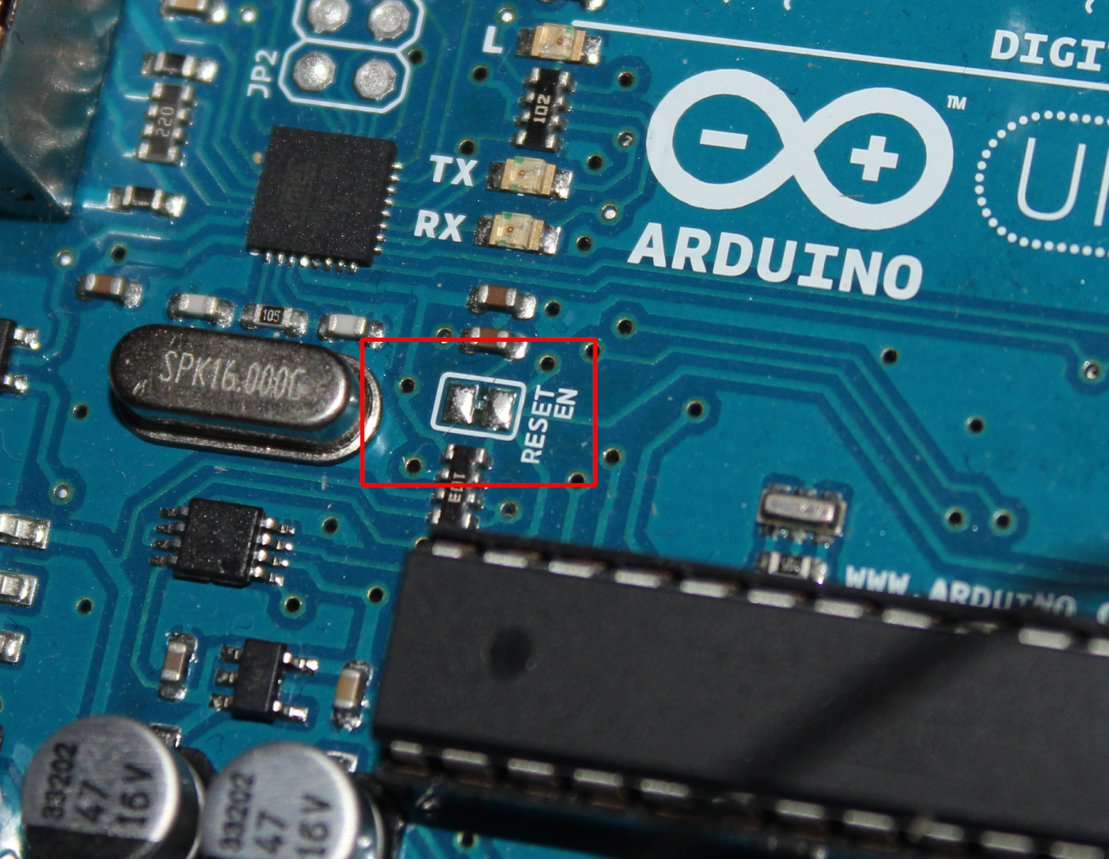
This connection must be disabled in order to disable auto-reset on serial connect.


Arduino Side


Let's have a look on the Arduino program first, and do a little walk-through:


It looks pretty complicated at first glance but that's only the appearance. First of all the usual stuff, I configure Timer 0 to CTC mode and unmask it's interrupt (one must remember to disable the Timer's 0 interrupt implementation in libpca - #define TDELAY_IMPLEMENT_T0_INT 0, since we're defining our own custom handler). In the while loop, Arduino is waiting for a complete SLIP frame, any junk frames (which size is smaller than the struct timer_data) are discarded, the last step is to verify the data checksum of the frame and to send a SLIP frame containing struct response with NACK status in case the CRC doesn't match. slip_verify_crc16() takes the buffer, it's length and third argument which defines a position in the buffer of the CRC checksum - in our case the CRC is placed at the very beginning, so the position equals zero. If the CRC verification is successful then at line 104 we can be sure that the data is genuine and not corrupted in communication. Next step is to reprogram the timer and finally send the SLIP frame with struct response with ACK status. This frame has a checksum calculated as well, and we will be able to verify it on the other side. The code is more or less straight forward.

The conclusion is that the LED attached to the Arduino will blink with different speed, and the "timing" details are programmed remotely through the serial line and the binary messages exchanged using SLIP protocol.

Host side


We can now focus on discussing the details of the host application. To be honest writing an IO application to communicate through the serial port in C for the host machine is a little bit tedious and quite time consuming, that's why it is far more convenient and simply quicker to create such tool in a scripting language of choice (Perl, Python, Lua) since most of the dirty work has been already done under the hood. For the purpose of comparison and education I'll present a script in Perl which will talk to our Arduino as well as in C.

Let's start with Perl since it's far more simpler and I believe it will be easier to understand.

Host Slip Communication in Perl


The biggest advantage of Perl over any other scripting language is CPAN and the amount of modules available. I'll use some of the already available building blocks in order to make my life a little bit easier. First of all we need to somehow use the Serial Port, the second thing is the CRC checksum calculation. We will need the following modules (they are available in Arch Linux package manager - which is my distro of choice, the package names are listed as well - those can be named similarly in your distribution):

  • Device::SerialPort (perl-device-serialport)
  • Digest::CRC (perl-digest-crc)

We've got the tools, we can do the work finally. Let's have a look on the following code:


For those who are not familiar with Perl it can be hard to get used to it. I'll try to be very verbatim. Starting from the top, the first interesting line is the declaration of hash %g_dev which holds the details of the Arduino's Serial Port. Again, for those unfamiliar with Perl hashes are like associative arrays, next I define the SLIP special characters as constants. Next are two important subroutines which realize the communication. First of all, Perl does not define something like a structure and does not provide a direct access to the memory underlying the variables - just like in C, how can we talk then about binary data interchange in a format described previously by the C structures ? It happens in a little bit different way. Perl provides two functions pack/unpack to pack the variables into a string accordingly to the given template and to unpack the string to variables accordingly to the given template (please read the details in the perl documentation, perldoc -f pack, perldoc -f unpack, perldoc perlpacktut). In order to make it more reasonable let's have a look on the struct timer_data once again. We need to send a byte stream constructed the following way:


  • crc16 - unsigned short 16 bit variable - pack template: S
  • prescaler - unsigned char 8 bit variable - pack template C
  • ocr - unsigned char 8 bit variable - pack template C
  • max_st - unsigned char 8 bit variable - pack template C

That means that if we would write:

my $data = pack ("SCCC", $crc, $prescaler, $ocr, $max_st);

or shorter:

my $data = pack ("SC*", $crc, $prescaler, $ocr, $max_st);


the pack function will assemble our variables into a string which can be then directly send through the serial port. We need something more here, the SLIP_END characters, so the complete call could look like this:

my $data = pack ("CSC*", (SLIP_END, $crc, $prescaler, $ocr, $max_st, SLIP_END));

That's exactly what is happening in the slip_send subroutine. First the data passed to it is scanned for any SLIP special characters in order to escape them. Once that is done, the original data (unescaped) is passed to the crc16 function to calculate the checksum. A word about line 32. First a byte string is constructed containing two zeros in the beginning - which are a placeholder for the CRC, and the rest of the data. The placeholding zeros are replaced with actual CRC once it is calculated. The receiver will calculate the CRC the same way in order to verify the data. It will copy the received CRC from the frame to the temporary variable and zero it's bytes in the frame - now the frame is in the same state as on the transmitter side before the transmitter calculated the CRC. If that operation wouldn't have place of course the checksums would be different.

The slip_recv() subroutine is exactly implemented the same way as in libpca. One thing of explanation here, slip_recv() has been implemented in more or less universal fashion - it takes a references to a getchar routine (line 38) which can be implemented over any kind of link. Next the command line input is parsed into global variables (lines 68-74), the serial port is initialized (lines 76-84) and we wait for 4 seconds. Now why is that ? As mentioned previously, after establishing a serial connection RS232 control lines will be toggled which in result will reset an Arduino, so we need to wait some time in order for Arduino to become ready and operational. By default (as it is visible in the code), the Arduino's Timer0 and Software timer will be initialized so the overflow happens with a frequency of ~ 1 Hz. The LED will blink with that frequency until the SLIP frame will be received with new configuration values for the timer. In lines 100-101 the SLIP frame containing our binary data is send over the serial line next the script waits for the SLIP frame from Arduino containing the response. The struct response is very simple, it contains only the CRC16 (2 bytes) and the status. It is unpacked after reception (line 107):

# unpack the serialized data to variables
my ($crc, $status) = unpack("SC", $data);

# calculate the checksum of the response for verification
my $crc_calcd = crc16(pack("SC", (0,$status)));

... and repacked again with CRC set to zero - the CRC is recalculated again for verification purposes. The last line simply presents the results.

Host Slip Communication in C


As far as our simple communication program was relatively short in Perl. We will have to dedicate much more effort in order to achieve the same in C (I imagine that everyone straight away lost their good mood now :)), but it's possible and sometimes it can be a better solution than any scripting language (small systems without any kind of interpreter available). Let's try to create functionally identical program in C. As previously we need some tools before we start

  • Serial Port IO and init routines
  • CRC16 implementation
The bad news is that we need to create those ourselves. Let's start with the CRC16 algorithm.

CRC16 checksum calculation


The best and  most comprehensive source for any algorithm or data structure implementation is ... linux kernel. Yes, that's right, everything that you will probably ever need is already implemented there and tested, just have a look at kernel's lib/ directory and pick what you need. I'm sure it will be there. The crc16 implementation is there for sure, we need the crc16.c file, slightly modified since we don't need the kernel specific stuff, have a look bellow:


Next, the serial port IO and initialization.

Serial port initialization


Serial port is a tty device, we need to initialize the speed, parity, flow control and other stuff through a termios API. I found this code some time ago and simply copy and paste it to my projects, there's no philosophy behind it, the tty_attrib_conf() initializes the port speed and other IO specifics, the tty_block_conf() configure, whether the calls to read() should block until the requested amount of data is collected. We will use the port by simply opening it (as like a file) and write/read to/from it using standard file IO API.


The last thing is the SLIP implementation itself. Of course I'm not going to duplicate it for the host application. Since it is already implemented in the libpca I'll use that implementation. Some preparations are needed though. libpca SLIP module expects to see common.h header file and config.h header file. We'll create dummy versions of those. config.h will contain:

#define SLIP_IMPLEMENT_CRC16 0

to disable the CRC implementation - it relies on the functions from avr-libc which of course are not available in libc/glibc for the standard GNU/Linux system. The common.h will contain the overriden IO functions:

#define SLIP_CHAR_SEND(__x) slip_sendc(__x)
#define SLIP_CHAR_RECV(__x) slip_getc(__x)

unsigned int slip_sendc(unsigned char a_char);
unsigned char slip_getc(unsigned char *a_data);

unsigned int slip_sendc(unsigned char a_char) {
/* printf("Sending char: %02x\n", a_char); */
return write(g_fd, (void *)&a_char, 1);
}

unsigned char slip_getc(unsigned char *a_data) {

unsigned char x = read(g_fd, a_data, 1);
/* printf("Recv: %02x\n", *a_data); */
return x;
}


The slip_send and slip_recv functions in the host application will use those to perform IO. Of course we need a Makefile to solve the inclusion paths and to make the whole project compilable. Finally our C application to send the binary data will look the following way:


Let's shortly walk through the code. First I open and create the file descriptor for the serial port (lines: 14-17), next two lines configure the port attributes and set the port to blocking mode. Next 5 lines (22-27) simply set the data in the struct timer_data which will be sent through the serial port to the Arduino. In line 30 and 31 the crc of the data packet is calculated and placed in the packet itself, finally on lines 42,43 and that's it.

How to use it ?


That's really simple. In order to test the examples presented bellow one can obtain etheir a project snapshot from here - it contains a snapshot of libpca and the source for the Arduino firmware (arduino_slip) - simply navigate to this directory and type make to build it and make install to flash it to Arduino. On the host side one can use either the host_slip.pl Perl script or build the application in host_slip directory by typing make. The application can be used the same way as host_slip.pl script.

It's possible to obtain all the sources from my public repositories from github in order to do that, one should

  • clone the newest version of libpca 
git clone git@github.com:dagon666/avr_Libpca pca
  • clone my Arduino projects repository 
git clone git@github.com:dagon666/avr_ArduinoProjects projects
  • navigate to projects/binary_slip
  • build both arduino_slip (remember to disable the TDELAY_IMPLEMENT_T0_INT in libpca config.h file since we are defining our own custom interrupt handler) and host_slip application
How to use the application ? After flashing the Arduino, regardless if we'll gonna use the perl script or the C app, the syntax is the same:

$ ./host_slip.pl 
host_slip.pl <prescaler> <ocr> <max_st>

The first parameter is the prescaler value (0-5), the second one is the value which will be placed in the OCR, and the last is the maximum value for the software timer, by invoking:

$ ./host_slip.pl 5 255 64

we'll program the timer to blink with a frequency around ~ 0.5 Hz. Experiment with the values. 

I hope that this article shed some light on the aspects of binary data exchange between the Arduino and any other machine and I hope that it proved that it's not that very difficult. Next time I'll try to present a project using this knowledge to build some more useful stuff.